Flex Breakout Board
The breakout board acts as a mediator between the hard electronics of the x-OSC and the soft e-textile sensors on the glove. It also provides PCB space for additional circuitry as well as a means of attaching and securing the x-OSC to the glove. What should the breakout board include?
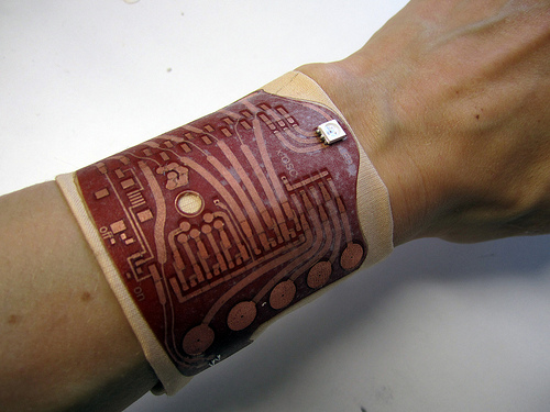
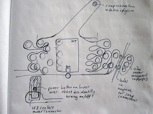
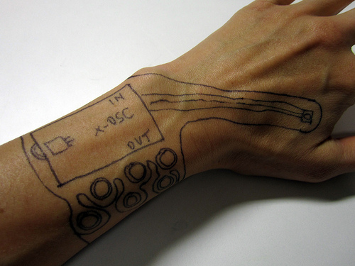
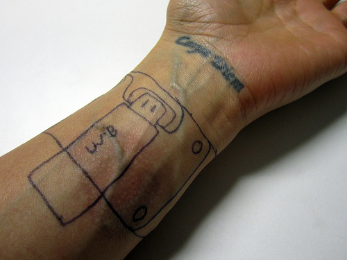
The flex circuit we’re looking to have made is basically a breakout board for a wifi i/o board called x-OSC that is mounted on the wrist of a dataglove. The flex pcb interfaces between the rigid PCB board and metal snap that connect to e-textile sensors as well as solder-pads for connecting the wires of some commercial flex sensors. The flex pcb also connects via metal snap fasteners to a vibration motor module, which will also be mounted on a separate small flex pcb. Other than a RGB LED, pads for pull-up resistors and a mini USB socket there is not much else on the flex PCB. The current design of the circuit is two-sided with the intention of fusing solder-masks to both sides, and some stiffening around the solder joints where the bend around the wrist occurs.
Eagle PCB files (Seb’s repo) >> https://github.com/xioTechnologies/Gloves-Flex-PCB
Eagle PCB files (Hannah’s repo) >> https://github.com/plusea/EAGLE/tree/master/projects/Gloves
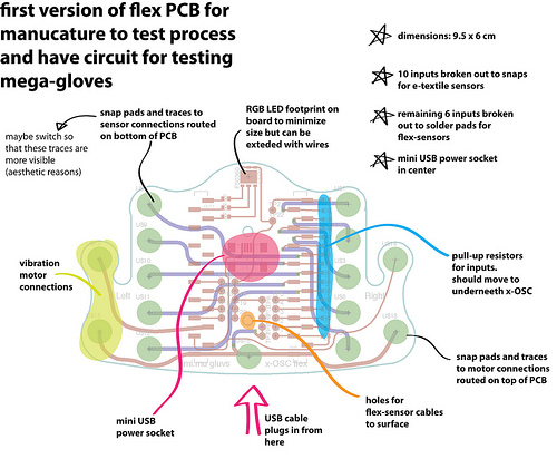
Version 1: Manufactured PCB
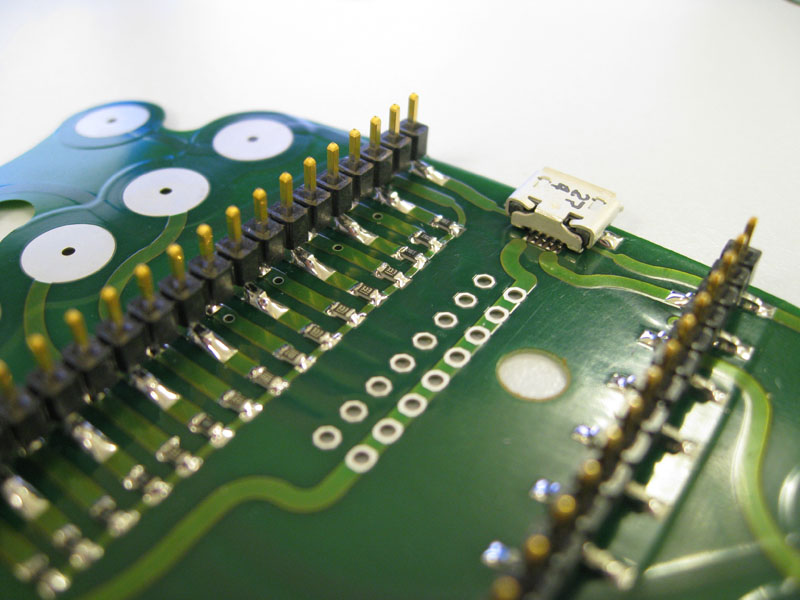
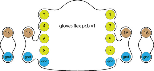
Summary of design: Surface-mount low-profile male headers for x-OSC connection with the following pins broken out:
- GND and VCC (3.3V)
- 10 input pins broken out to snap pads (with pull-up resistors)
- 6 input pins broken out to pads for additional sensors (with pull-up resistors)
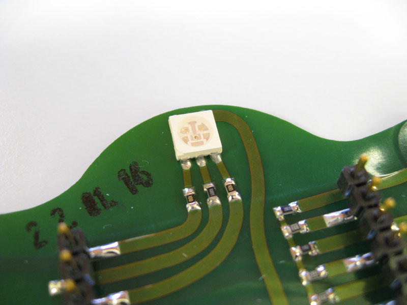
- 3 output pins broken out to RGB led (with resistors)
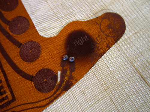
- 2 output pins broken out to left and right vibration motor
- 11 output pins left unconnected
USB micro plug connected to power x-OSC (USB mini location conflicted with JST from x-OSC).
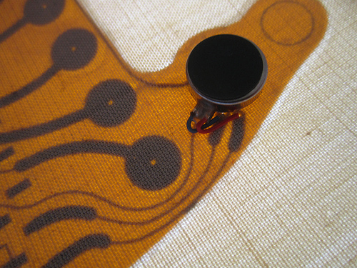
Two additional small flex PCBs for vibration motors.
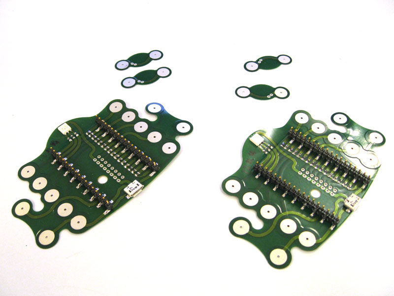
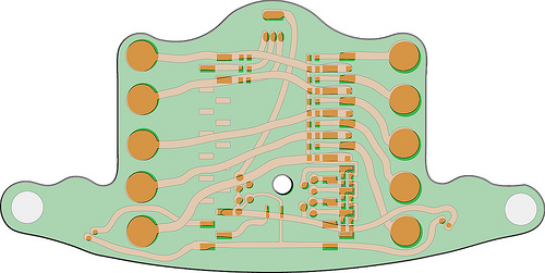
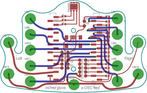
Populated boards:
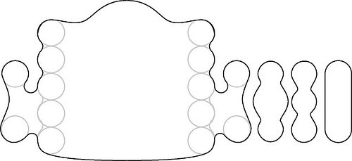
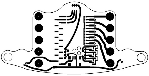
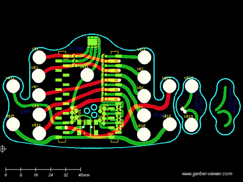
Unpopulated boards bottom (left) and top (right) views:
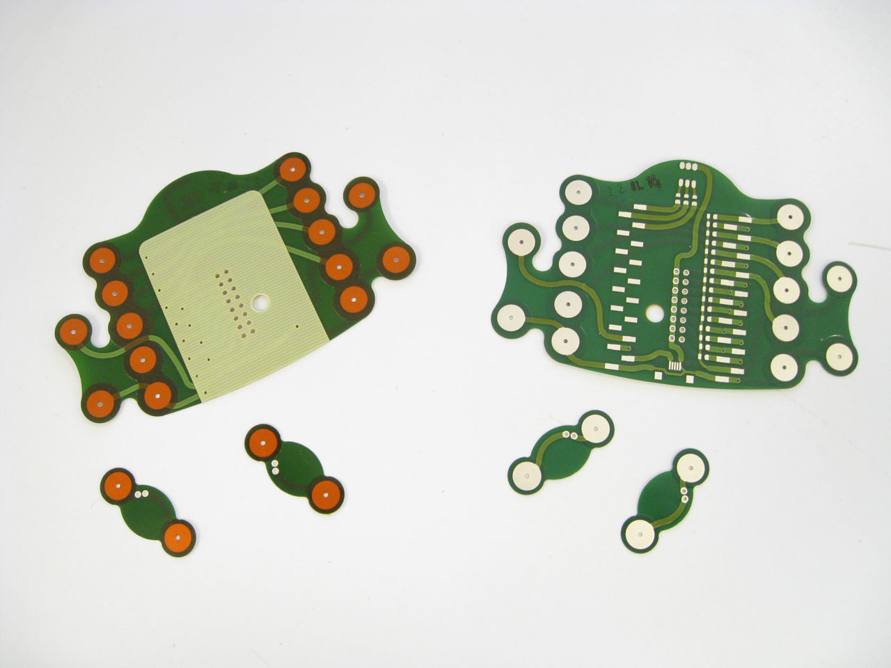
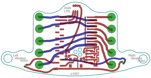
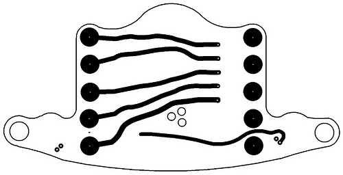
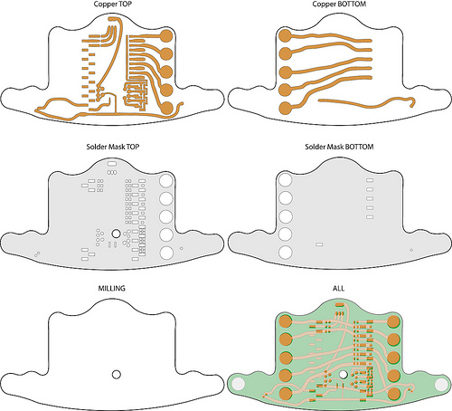
Copper layers (top=red, bottom=blue):
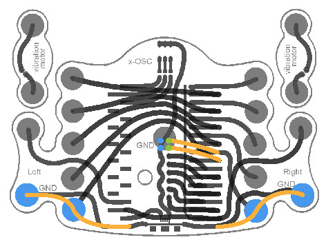
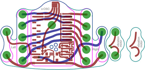
Connections (green=inputs, brown=outputs):
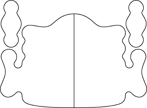
Shape drawn in InDesign:
Corrections:
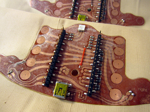
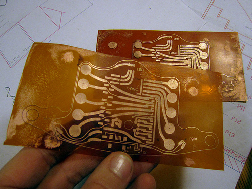
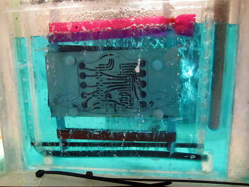
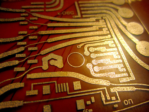
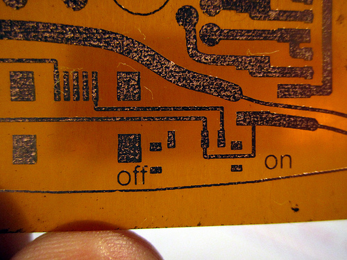
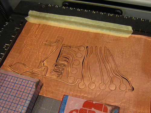
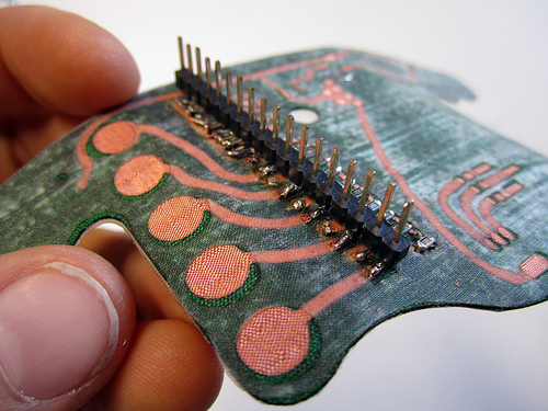
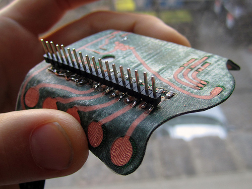
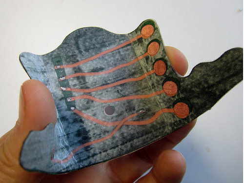
Version 0.6: Etched PCB
Materials:
- Etched copper flex board (kapton base?)
- Silk backing for reinforcement
- Silk soldermask
- HeatnBond fusible interfacing
Parts:
- RGB LED (sparkfun)
- SMD resistors for RGB LED (red = 68 Ohm, green&blue = 10 Ohm)
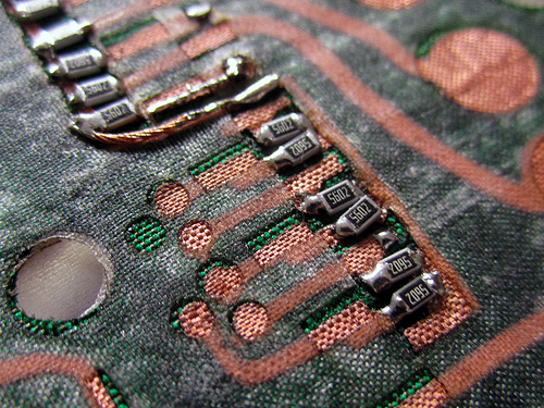
- SMD resistors for E-Textile sensors (100 K Ohm)
- SMD resistors for Flex sensors (220 K Ohm)
- Surface mount male headers 90° angle
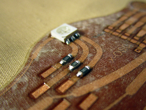
RGB LED details:
Red: 2.0-2.5V ->> 68 ohm
Green: 3.1-3.8V ->> 10 ohm
Blue: 3.1-3.8V ->> 10 ohm
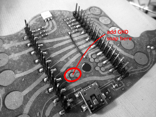
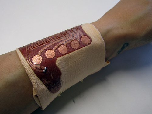
OPS! I forgot to add a GND snap
Quick fix: add snap to broken-out ground solder pads intended for flex sensor cables. As shown here:

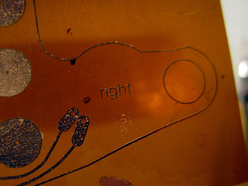
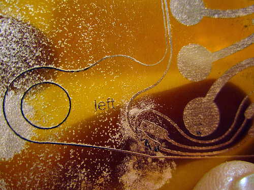
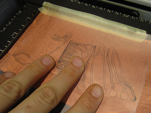
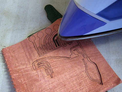
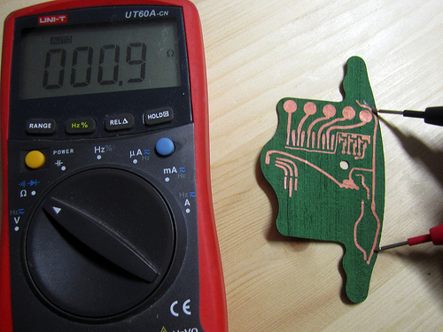
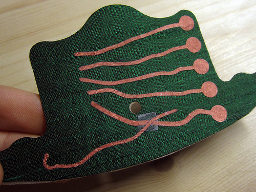
Version 0.5: Lasercut fabric PCB
Materials:
- Kassel copper plated conductive fabric from Statex
- Green silk as base material
- White translucent silk as solermask
- HeatnBond fusible interfacing
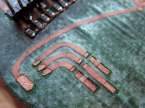
Fabric PCB

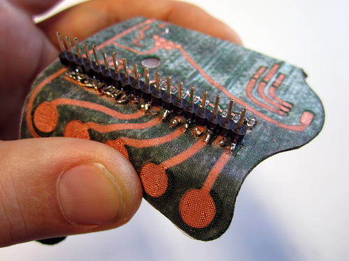
Making:
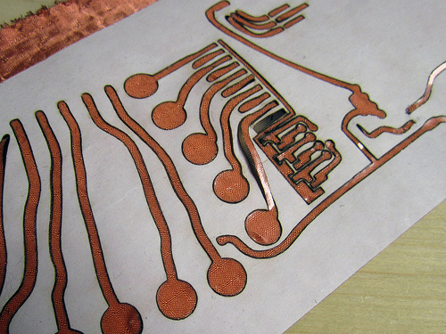
Back:
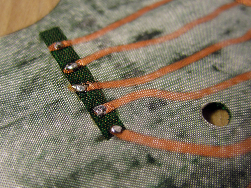
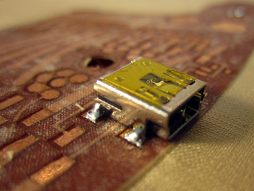
Solder close-ups:
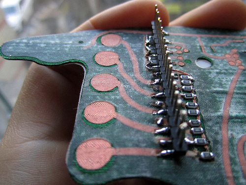
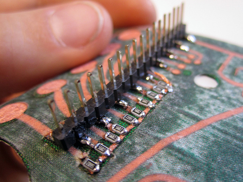
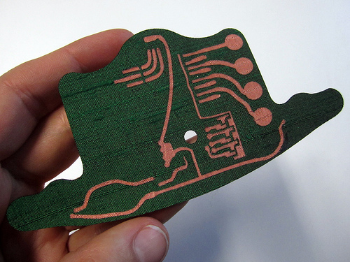
Too stiff - not really flexible:
Eagle and Cut Files
Motors are soldered directly on board and snaps just hold flaps down in place.
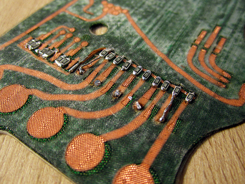
Top and Bottom:
Version 0.4
Sent for quotes to Andus Elektronik in Berlin and Seb’s manufacturer in UK.
Version 0.3: Sketches and PCB Layouts
Eagle files (V3!)>> https://github.com/plusea/EAGLE/tree/master/projects/Gloves/xOSC%20Gloves
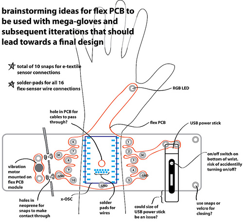
What to include???
- surface-mount header footprint for x-OSC to connect to
- USB mini and micro sockets for power
- JST socket for power - NO
- on/off switch for power supply to x-OSC - NO
- LiPo charging circuit and USB connector - NO
- pull-up resistors/voltage dividers for flex sensors and e-textile sensors
- RGB LED
- resistors for RGB LED
- vibration motors
- snap connections to e-textile sensors
- solder or plug connections to flex sensors
- additional input/output pins broken out to a connector
- ATtiny or other chip (or even just footprint for chip) that could allow for i2C interfacing with hardware - NO
- hole in center of breakout board for flex sensor wiring to come through
- should whole design be kept symmetric so that the same PCB can be used for both left and right hands?
Flex circuits from China
“Depending on size and requirements, it starts at like $50 and goes up to a couple hundred for the first 10. I’ve never really taken anything to production with them so I’m not sure what prices look like then. Turnaround was about a week and quality was good.” (from Zack)
>> http://item.taobao.com/item.htm?id=16489578286
[…] >> http://theglovesproject.com/flex-breakout-board/ […]
Hi
Just noticed your project and the involvement of our product.
Not sure what your goal is but good luck!