Step 7: Connecting the Bend Sensors
This step explains how to connect the bend sensors to the wires that have already been sewn to the wristband-circuit of the glove as well as to add additional GND wires to each sensor and cluster them together to the GND wire of the wristband-circuit.
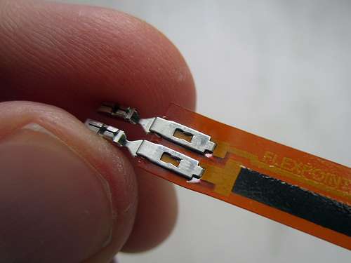
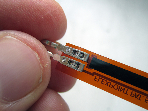
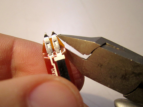
If the bend sensors that you ordered came with blue sockets on them, then you need to remove these before you can continue with this step.
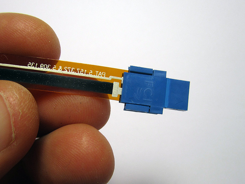
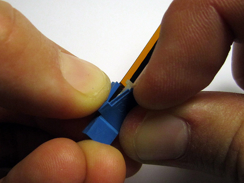
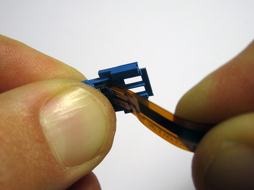
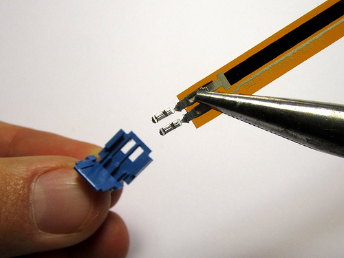
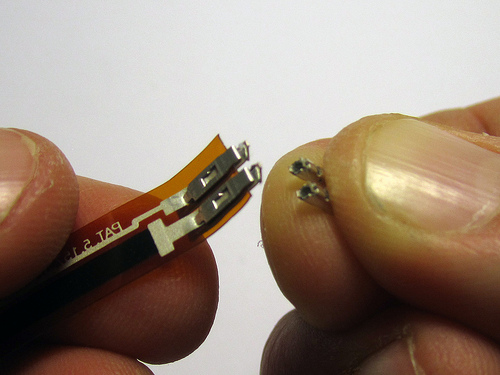
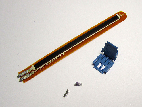
Video of how to remove the blue socket from the Flexpoint bend sensors
Don’t forget: these gloves are customizable! You do not need to use all 6 bend sensors as used in this design. Instead you could implement other analog or digital sensors such as pressure sensors, tilt sensors or contact switches. You can also mount the bend sensors on different fingers and knuckles, or even on the wrist.
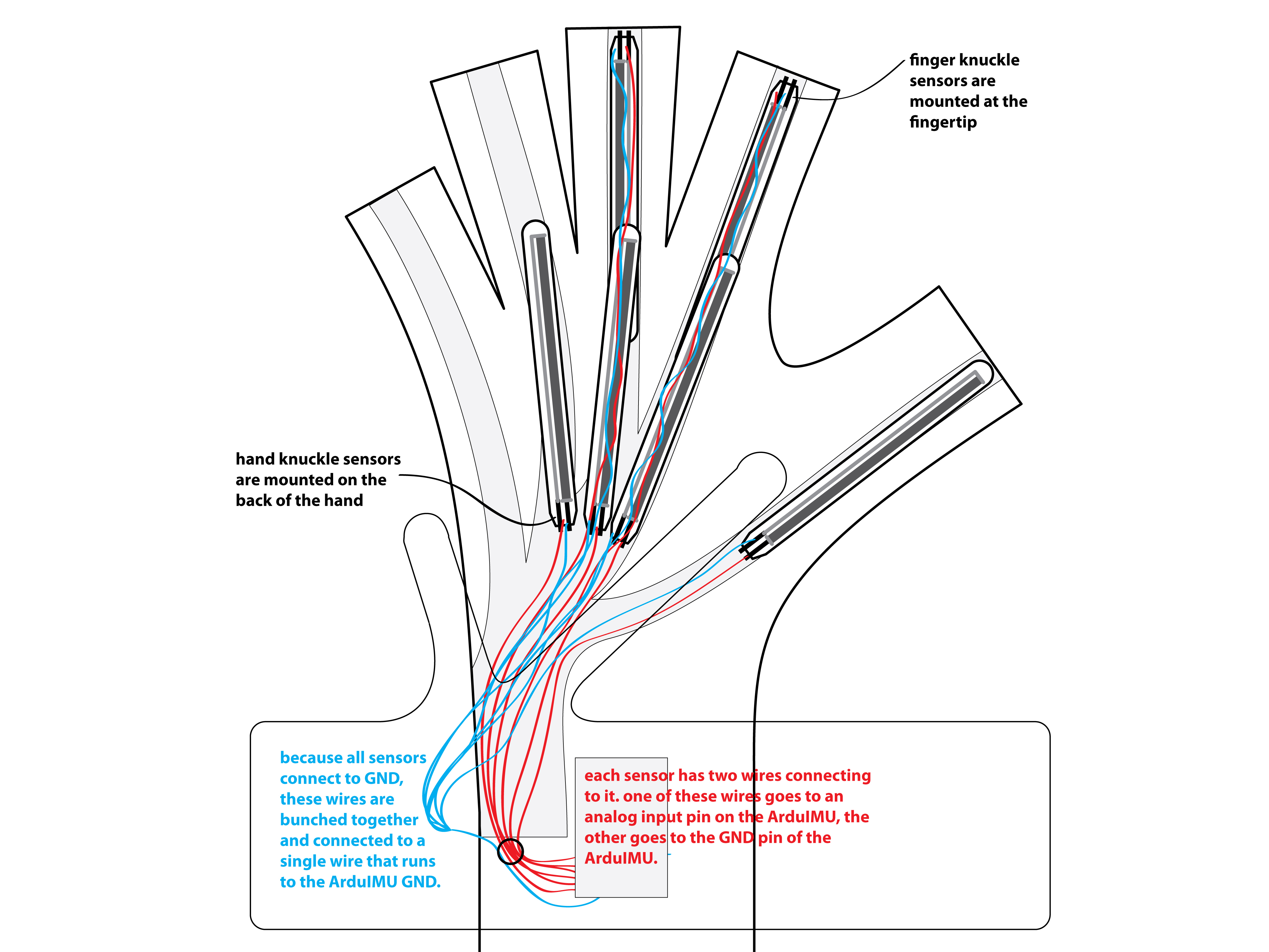
The following illustrations show how to wire the 6 bend sensors used in this design.
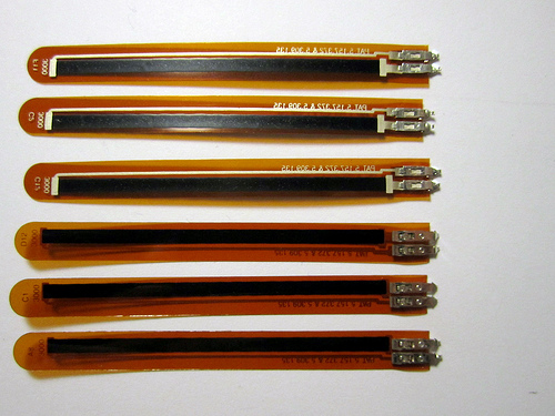
Placement of sensors: all sensors are the same length (3 inches). 4 of the sensors are mounted over the hand knuckles of the ring, middle, index and thumb. 2 of the sensors are mounted over the hand knuckles of the middle and index fingers.
Wiring of sensors: Each sensor is wired with two connections. One of these connections goes to an analog input pin on the ArduIMU. The other connection goes to GND (ground, minus, negative) on the ArduIMU.
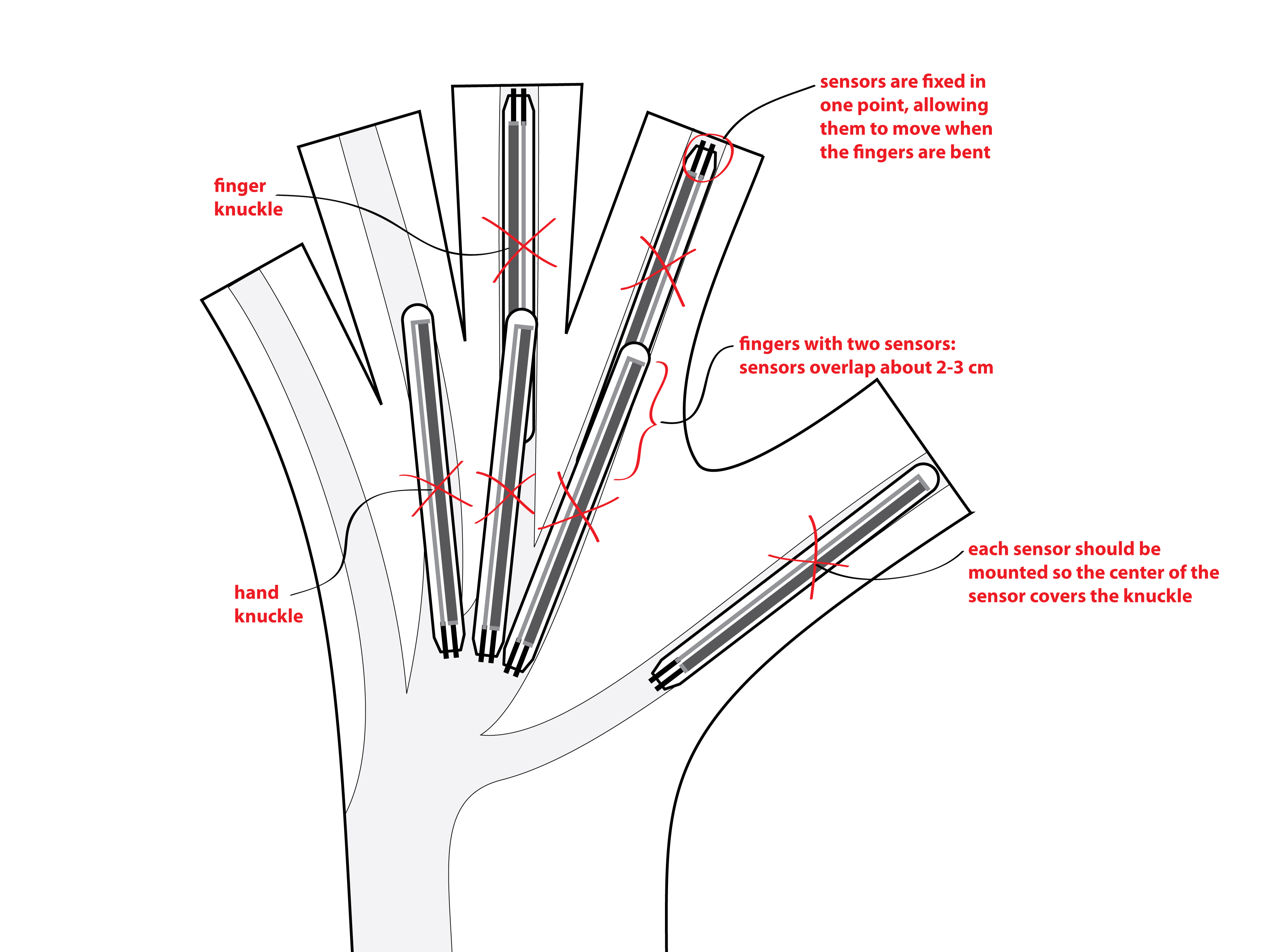
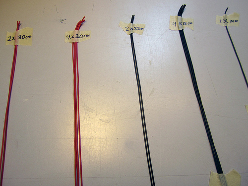
Sensor wire lengths: Because some of the sensors are mounted close, and some further away the length of the bend sensor wires need to be different lengths. The following illustrations shows the logic behind the wiring lengths. The lengths do not have to be exact, but they are roughly the following:
2 x 30cm (analog input wires to middle and index finger knuckle sensors)
4 x 20cm (analog input wires to ring, middle, index and thumb hand knuckle sensors)
Black wires:
2 x 25cm (GND wires to middle and index finger knuckle sensors)
4 x 15cm (GND wires to ring, middle, index and thumb hand knuckle sensors)
1 x 10cm (GND wire from bundled GND wires to ArduIMU GND connection) — mistake in illustration, this wire should be 10cm long not 5cm!
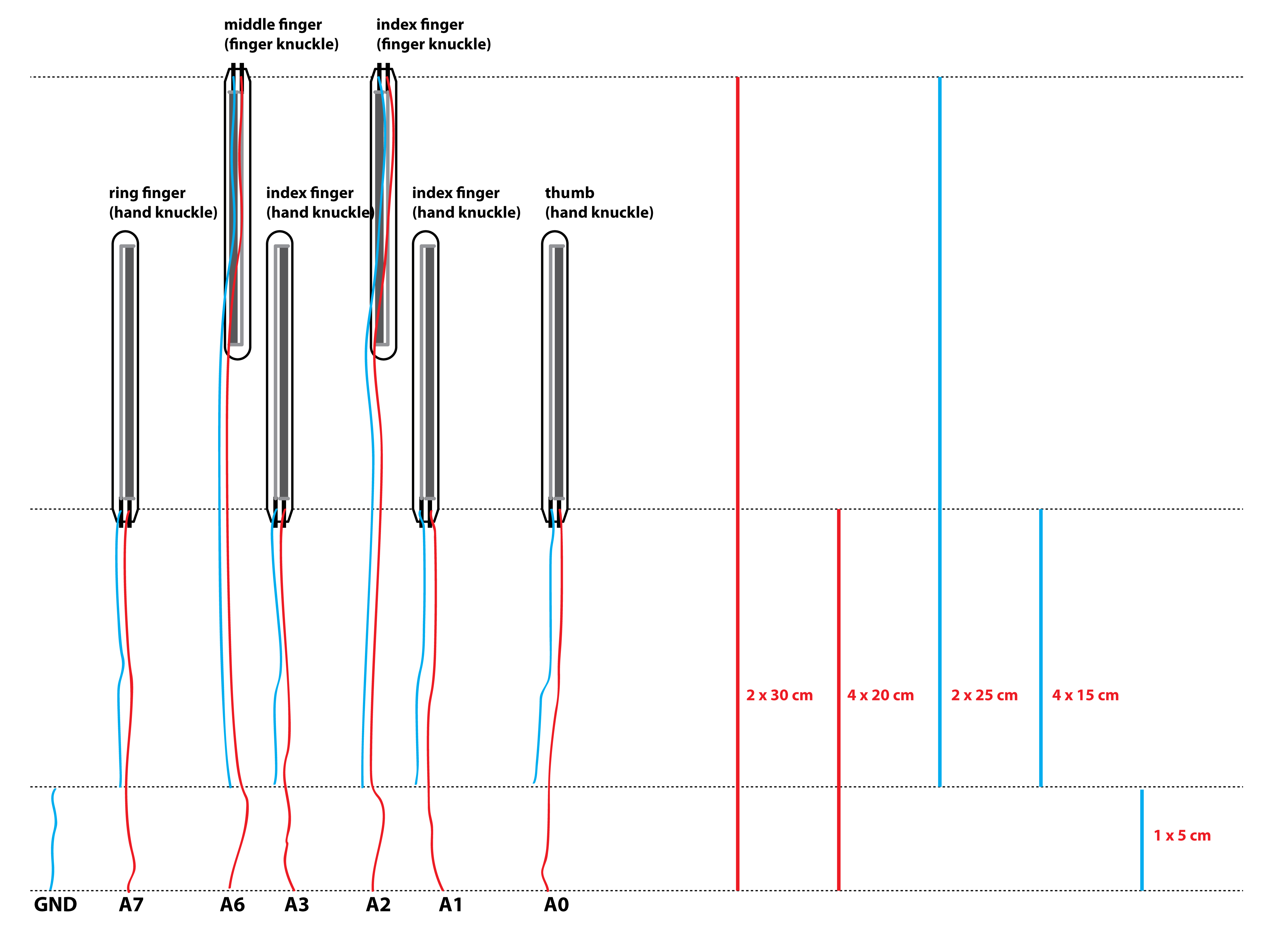
Note also that the sensors should be connected as follows:
A0 — Thumb
A1 — Index (hand knuckle)
A2 — Index (finger knuckle)
A3 — Middle (hand knuckle)
A6 — Middle (finger knuckle)
A7 — Ring (hand knuckle)
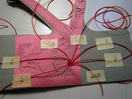
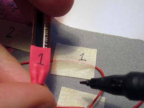
Get organized. Trace each of the wires back through the hole to which analog input it is connected to on the ArduIMU and mark this on a piece of masking tape. Also you can lay-out your bend sensors and mark them:
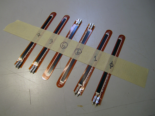
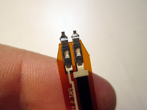
Understanding which is the top, and which is the bottom side of the sensor:
Top, Bottom
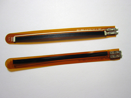
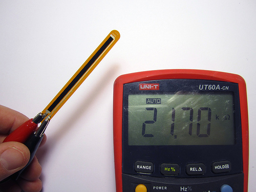
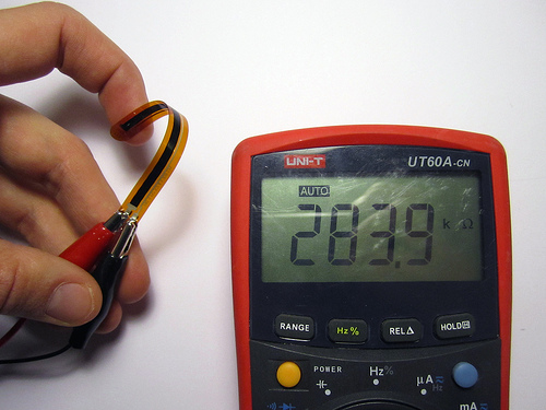
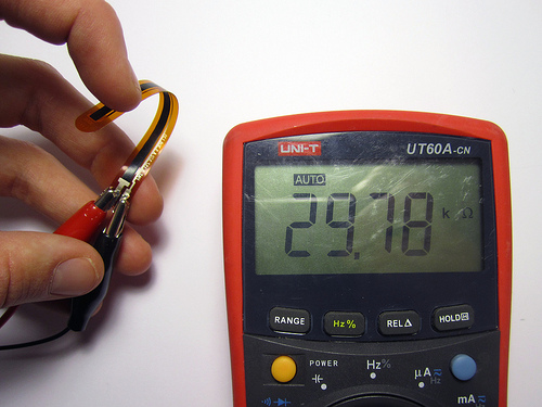
Resistance range of sensors:
Relaxed (straight) = ca. 20K Ohm
Bent (right way) = ca. 300K Ohm
Bend (wrong way) = ca. 30K Ohm
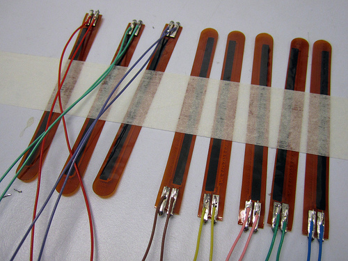
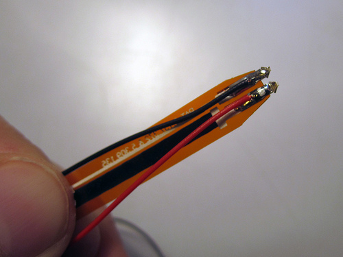
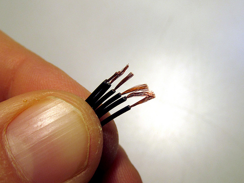
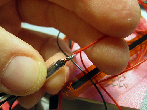
Use the wire-cutters to clip off the corners of the bend sensors:
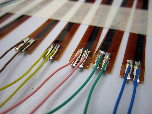
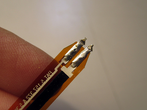
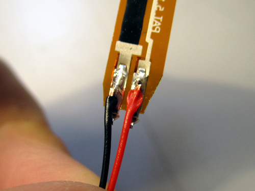
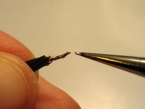
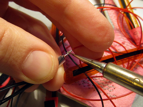
Add solder to the bend sensor leads as well as to the wire ends before bringing both together and soldering them to make the connections:
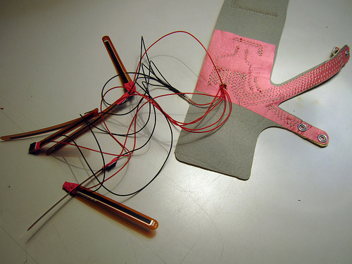
Here are some photos of the bend sensors prepared for a previous pair of gloves where I did not first sew the analog input wires to the wristband. Using different colours for each bend sensor is another way of keeping track which one should go where.
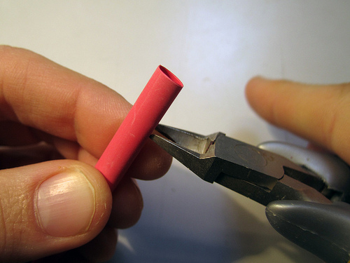
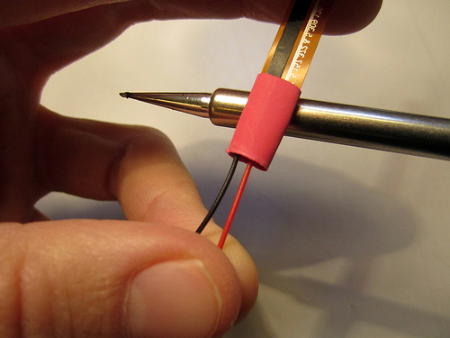
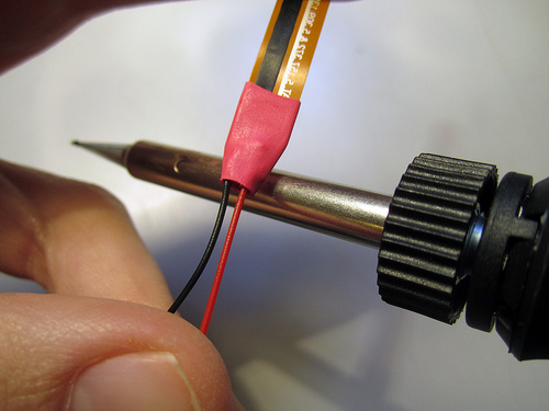
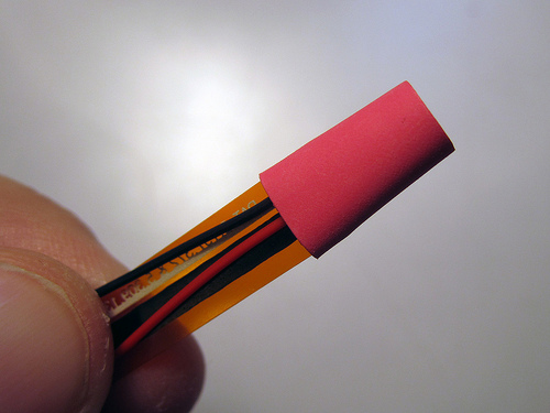
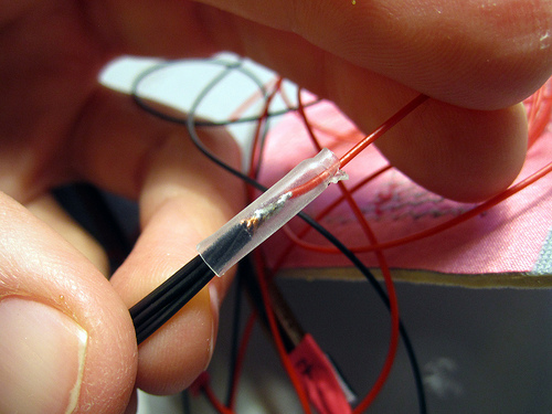
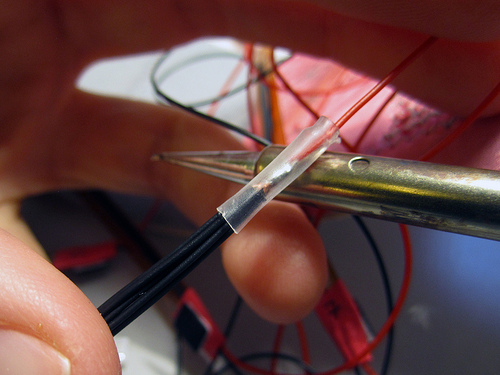
Cut a piece of shrink-tube to size and place over solder connection. Use lighter or soldering iron or other appropriate heat source to shrink heat shrink tube.
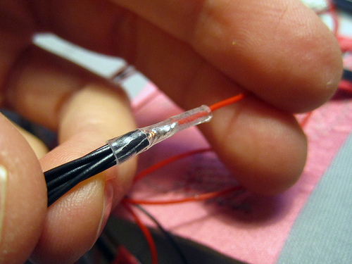
For the two sensors on the finger knuckles you want to solder the wires on so that they lead off over the sensor, rather than directly away from it as previously:

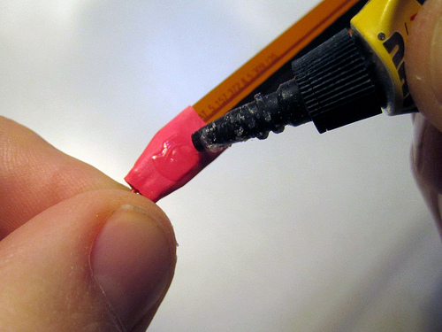
After adding heat shrink to all sensors, cut small pieces of neoprene and superglue them to the bottom side of the sensor on the shrink tube. This is so that you can then attach the sensor to the fabric of the glove after you have inserted it into the veins.

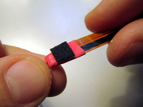
Transfer the numbers from the masking tape to the shrink tube so that you don’t loose track of which sensor should go where:
typo: attching->attaching
[…] The 6 wires that connect to the analog pins of the ArduIMU need to be cut long enough so that the bend sensors soldered on the other end of them can be mounted over the finger and hand knuckles inside the veins of the glove. For the wires going to the analog inputs cut two 30cm long wires and four 20cm long wires. For the wire that goes from the ArduIMU GND to the bend sensors cut one 5cm long wire. The following illustration shows the logic behind these lengths. And you will also find a more detailed description of the bend sensor wiring in the step titled “Connecting the Bend Sensors”. […]
Hannah, the heat shrink hasn’t sofar been included in the materials list.
thanks!
Barbie will be half a century old in the year 2009. She was introduced in 1959 at the New York toy fair. Barbie 1 wore a zebra striped one piece swimsuit,high heeled,open toe,shoes and had either blonde or brunette hair.
do you have any of these gloves available? I would like to use them on one of my robot arms. via the internet… I WOULD build them just don’t have time at the moment.