Step 6: Soldering Connections
This step explains how to solder the wires of your sewn wristband circuit to the various parts, including the metal snaps, LED module and the ArduIMU.
Soldering to Snaps
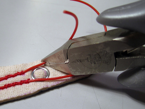
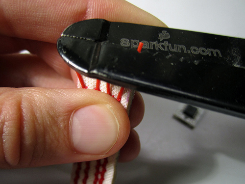
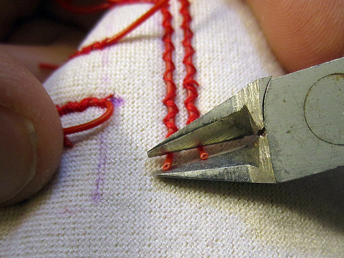
Trimming and stripping wire:
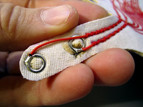
Right hand:
Video: Soldering to snaps
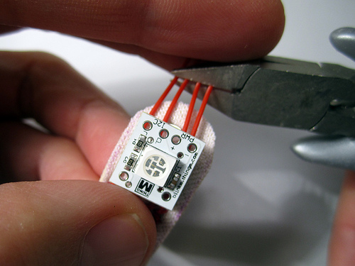
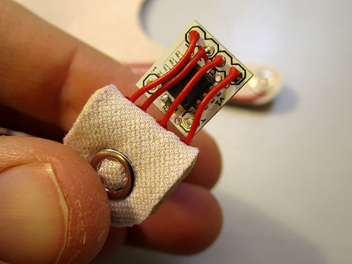
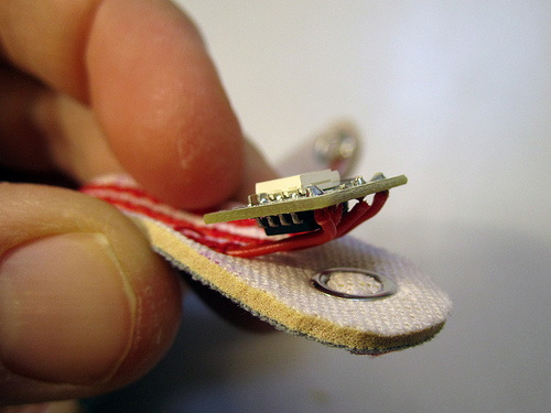
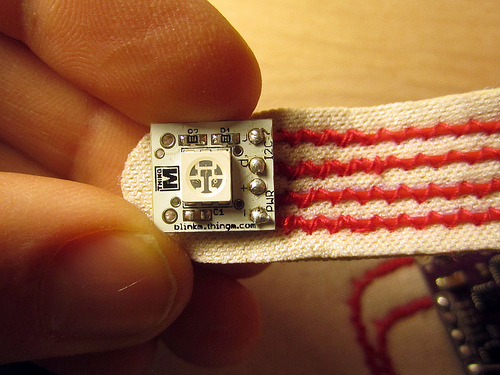
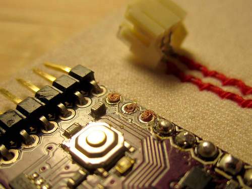
Solderieng Wire to RGB Module
This photos show how the RGB module of the left hand needs to be connected. CAREFUL: The RGB module of the right hand needs to be connected the other way around. Make sure that you are always connecting it as follows:
RGB LED Module — ArduIMU
+ — +
GND (-) — GND (-)
C — SCL
D — SDA
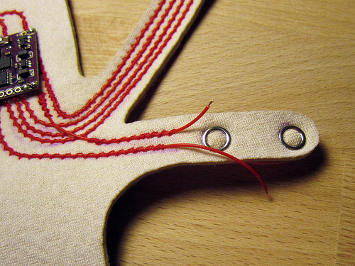
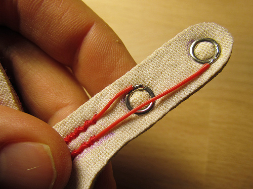
Trimming and stripping wire:

Right hand:
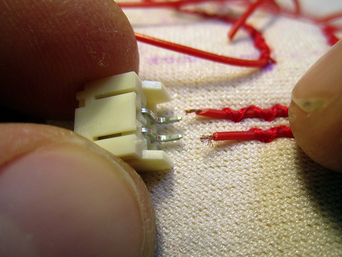
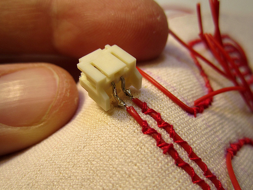
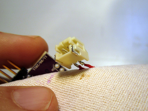
Soldering to JST Socket
Trimming and stripping wire:
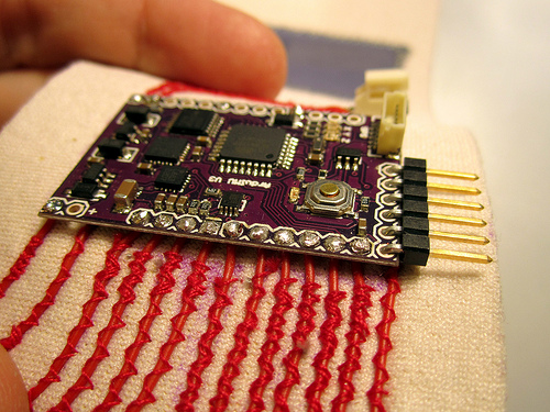
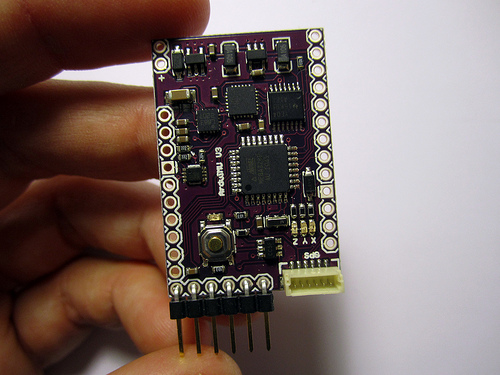
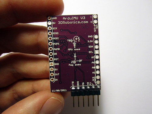
Soldering Headers to ArduIMU
Before you solder the ArduIMU to the wire circuit you have sewn on the neoprene wrist band you need to solder a connector to the FTDI pins of the ArduIMU!
These are the pins that you will then use to connect the wired or wireless (Bluetooth) connection.
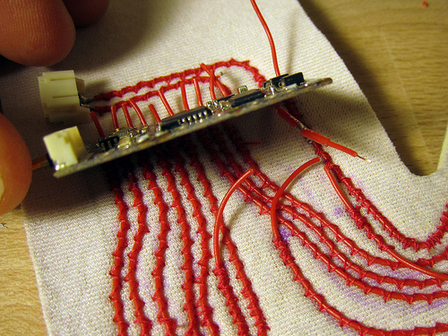
Soldering Wire to ArduIMU
Front and back of ArduIMU:
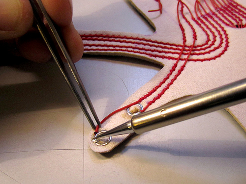
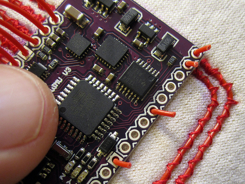
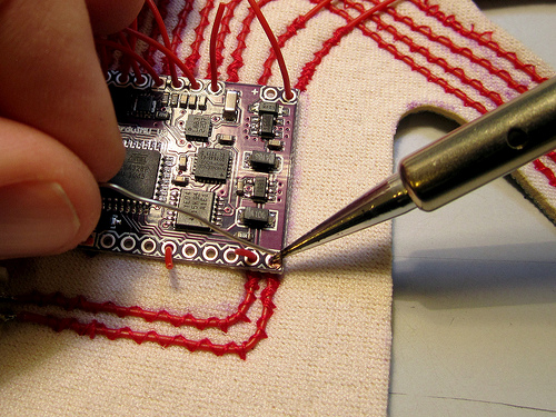
Use tweezers to insert wires through holes of PCB:
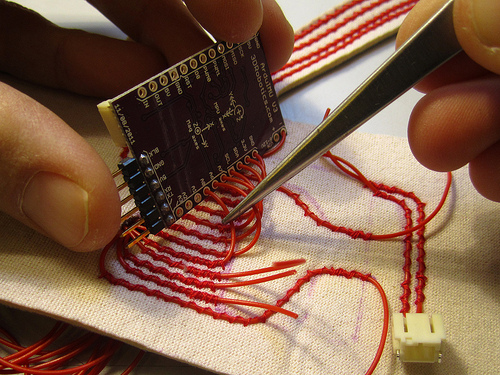
Trim the wires to about 6mm above the surface:
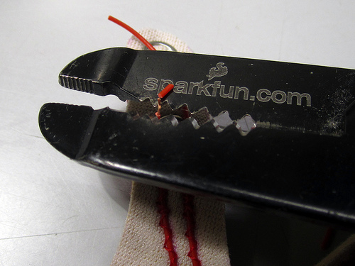
Use the cutter knife to nick the insulation without damaging the wire. Pull of insulation. This is a tricky part.
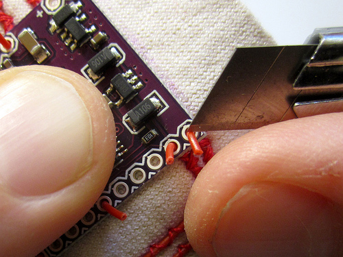
Use the tweezers to mash around the wire into a clump that does not go beyond the metal surface you want to solder it to. This is another tricky part!
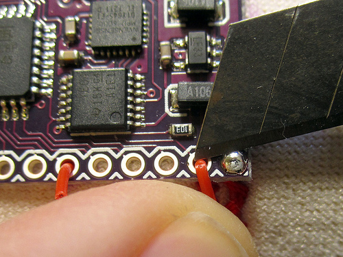
Now solder. With all the preparation done neatly, this should be simple.
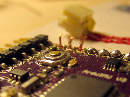
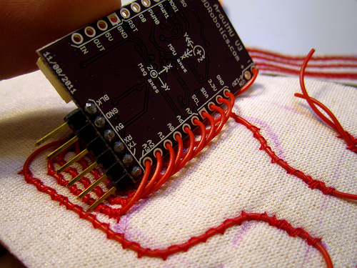
Twirling stripped wires for soldering to ArduIMU
Soldering twirled wires to ArduIMU
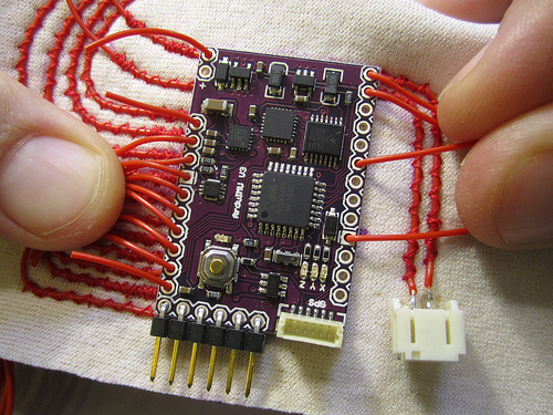
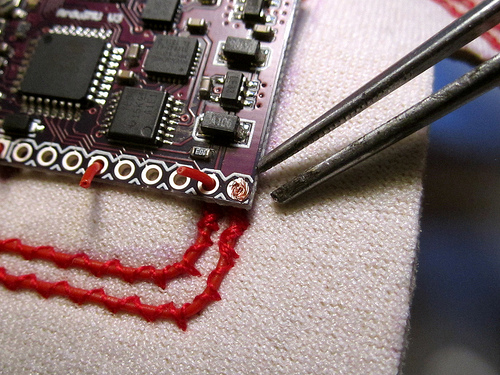
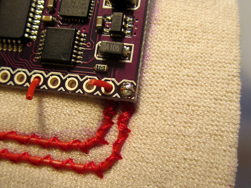
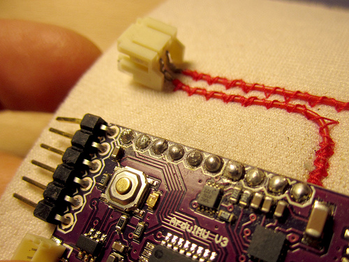
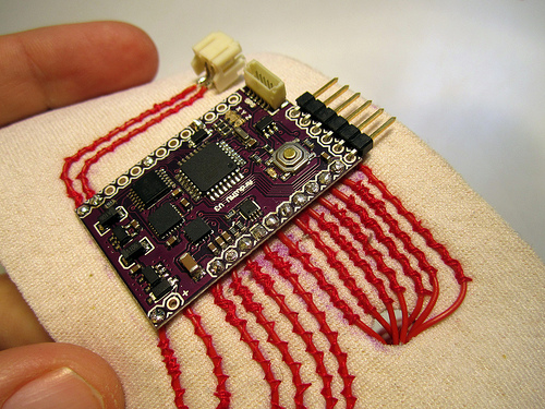
When you are done, take a close look at all your connections and make sure that everything is tidy like in the pictures bellow:
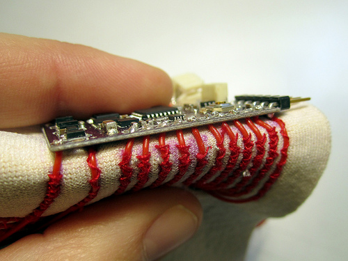
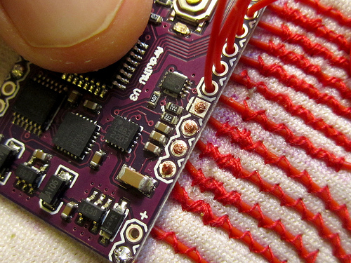
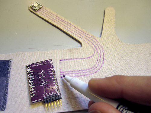
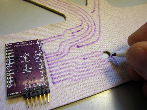
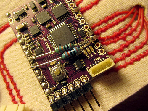
Because the ArduIMU circuit boards are not mirrored but our bodies and hands are, we need to account for this difference in the circuit layouts for the left and right hands. As most of the instructions in this DIY tutorial refer to the left hand glove. One main difference between the left and right hand circuits is that on the right hand circuit the wire connections from the analog inputs to the bend sensors will run underneath the ArduIMU circuit board as shown in the following photos:
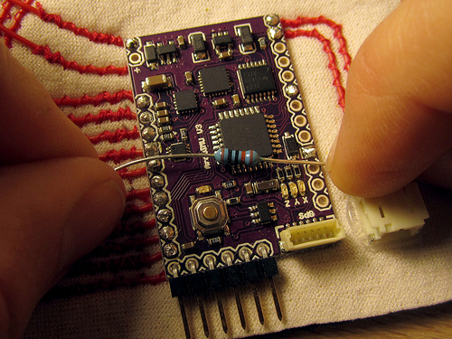
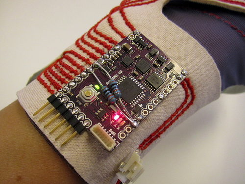
Soldering Pull-up Resistors
The ArduIMU has 6 analog inputs which we use for reading the values of the bend sensors. But only 4 of these analog inputs (A0, A1, A2, A3) have internal pull-up resistors (see: voltage dividers) built into the microcontroller which can be turned on in code. This means that for the remaining 2 analog inputs (A6, A7) we have to connect our own (external) pull-up resistors. Because the range of the Flexpoint bend sensors is about 20K-300K Ohm, we use 100K Ohm resistors that are connected between the analog input pins A6, A7 and VCC (up).
CAUTION! When placing the sensors make sure that their leads do not make contact with any other metal contacts of the components on the ArduIMU circuit!
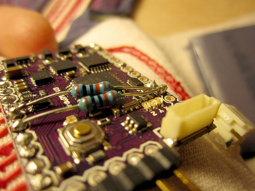
Left and right hand circuits with pull-up resistors going between analog pins A6, A7 and VCC.
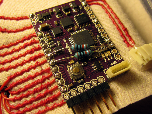
Soldering pull-up resistors
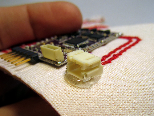
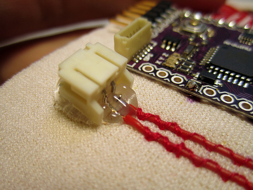
Hot-gluing JST Socket
Apply hot glue underneath the JST socket, make sure to get some on the actual solder connection and even on the wire insulation. Press down the socket to the neoprene. And make sure that the hot glue does not get inside the socket!
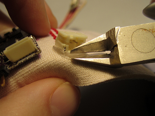
You can trim away excess hot flue after it has cooled with the wire clippers.
Test Your Circuit!
Using a multimeter set to measure continuity go over your circuit and make sure the following:
…
If all looks good with the multimeter, you can now plug-in the battery lead to the JST socket. The ArduIMU should come on. If it does not, then unplug it again quickly but carefully. Wiggle the plug back and forth while pulling at it gently. Unfortunately these connectors are not the best design.
Hannah,
Are you sure about the 100 kOhm?
Somehow the colors in the image look differently.
Hannah,
You wrote: “Because the range of the Flexpoint bend sensors is about 20K-300K Ohm, we use 100K Ohm resistors that are connected between the analog input pins A6, A7 and VCC (up).”
If one looks at the formula for the voltage divider then it seems: U_bend = R_bend/(R_bend R_pullup) * U_VCC
So if one would like to maximize the range of the voltage U_bend as a function of R_pullup, one would like to maximize the function:
Range(x)=U_bendmax(x) - Ubendmin(x) = [R_bendmax/(R_bendmax x)-R_bendmin/(R_bendmin x)]*U_VCC
or in other words one wants to find the solution to the the equation d/dx Range(x)=0.
The positive solution to this is x=sqrt[R_bendmax*R_bendmin] which is for
R_bendmax=300kOhm and R_bendmin=20kOhm about 77kOhm, however since the bend
sensors are going to be bend only to about 90 degrees (due to the limited range of the finger knuckles…), one rather has approx. R_bendmax=150 kOhm. So following this it seems the optimal resistor would be rather in the range of 50kOhm. Is this correct?
As a side conclusion it seems that if one would use bend sensors in different ranges than the Flexpoint ones above, then the software pull ups for the other inputs might be less suitable and one would probably be better off if one would solder appropriate pullup resistors as a replacement for those in order to maximize the range and thus the resolution the data glove.
Hannah, either I did a typo in the above in the formulas for the voltages or the comment environment swallowed a plus sign. Anyways it seems the formula for the pullup resistor might be quite useful in various applications and I hadnt found it on a quick search, so I wrote now the above into wikipedia:
http://en.wikipedia.org/wiki/Pull-up_resistor#Sizes_of_pull-up_resistors_in_circuits_with_sensor
please check if its correct.
Why you sew over normal wire instead of use conductive wire directly for the connections?
why you sew over normal wire instead of use conductive wire for the connections?
I was going through the DIY pages here when I found that the page for ‘step 6′ was missing. Does that step have any vital information? It didn’t look like it did, but I’m only reading through to get an idea for the project, at this point.